
Echometer Total Well Management System
$19,900.00


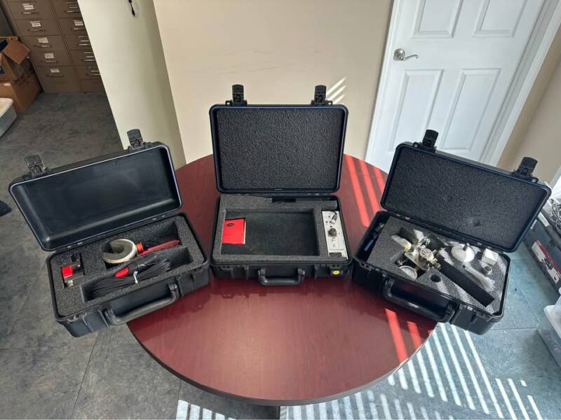
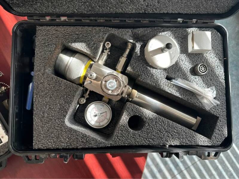
Echometer Model E (TAM, Pressure Transient, & Plunger Lift Analysis Equipped), 1500 PSI Remote Fire Well Head, Pressure, Polished Rod, and 4” – 30K Horseshoe Dynamometer Transducers
All original cables, hoses, and chargers included.
This is the whole shebang. Over $40K USD out the door, new. Upon purchase, setup will be sent to Echometer for inspection, and a “clean bill of health” will be provided to purchaser prior to shipment.
The TAM and / or TWM software is available to anyone free to download from Echometer.
The Well Analyzer is an integrated artificial lift data acquisition and diagnostic system that allows an operator to maximize oil and gas production and minimize operating expense. Well productivity, reservoir pressure, overall efficiency, equipment loading and well performance are derived from the combination of measurements of surface pressure, acoustic liquid level, dynamometer, as well as power and pressure transient response. The Well Analyzer acquires, stores, processes, displays, and manages the data at the well site to give an immediate analysis of the well’s operating condition.
The upgraded pressure transient option can be used to obtain pressure buildup data. The operator programs the Well Analyzer to acquire data points while unattended. The rate may be specified in either shots per hour or shots per log cycle. Numerous diagnostic and analysis plots are available including casing pressure vs. time, liquid level vs. time, bottomhole pressure vs. time, log-log plot with derivative, Homer plot, MDH plot and radial flow type curves. Real time viewing of the plots ensures that the wells are returned to production as soon as the test objectives have been reached.
The plunger lift analysis software can be used to acquire acoustic and pressure signals from a gas gun attached to the tubing. Pressure data from an additional pressure transducer attached to the casing can optimize the performance of a plunger lift installation. At any point in time during the Plunger Lift’s operation cycle, both the position and velocity of the plunger can be accurately determined using this equipment. Monitoring the tubing and casing pressures allows the calculation of gas and liquid flow rates into and out of the casing and tubing, and also the varying flow rates as a function of pressure from the reservoir. Plunger trace measurements help to ensure that the plunger will reach the bottom of the tubing by the end of the shut-in time period so that all of the liquid in the tubing can be lifted to surface during the plunger unloading cycle. By accurately measuring the plunger fall velocity, the proper shut-in time for the plunger lift installation can be determined. Setting the well to have the shortest possible shut-in time period to allow the plunger to fall to bottom will maximize oil and gas production from plunger lift installations.
Both the Pressure Transient & Plunger Lift software include all necessary elements for acquisition and interpretation of the data and generation of reports and transfer to external databases. Each software package’s firmware is flashed into the memory of the analyzer.
The load and position data gathered by the polished rod transducer allows for the software analysis of polished rod power requirement, pumping unit beam loadings, rod loadings, pump power requirements, and pump performance, as well as calculation and determination of a surface dynamometer card, a pump card and traveling and standing valve tests. This transducer obtains dynamometer data that is sufficiently accurate for most pumping unit analysis with minimum effort, with an install time less than 30 seconds. The polished rod transducer is simply clamped to the polished rod below the carrier bar.
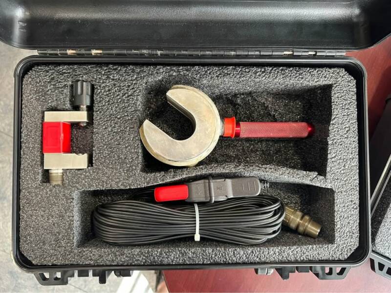
The horseshoe load cell transducer is used to very accurately measure the polished rod load and position. This data is processed by the Well Analyzer software to obtain a surface dynamometer card and pump card. The loads and horsepower requirements of the surface dynamometer card and the pump card are both shown in the software analysis. A traveling valve and standing valve test can be performed. The standing valve test measures the polished rod load when the rods are supported by the liquid in the tubing. A comparison of the measured load to the calculated buoyant rod weight is an excellent check that the well’s rod data are entered correctly. The traveling valve and standing valve tests allow the calculation of pump intake pressure, pump leakage, traveling valve and plunger performance and standing valve leakage performance. Gearbox loading is calculated by software using the polished rod load and position data. The counterweight moment must be calculated using the known properties of the cranks, counterweights and counterweight positions or the counterweight moment can be determined by measurement of the counter balance effect using the accurate 4″ horseshoe transducer. Gearbox
| Street | P.O. Box 553 |
| City | Mount Carmel |
| State/Province | IL |
| Country | United States |
| Zip/Postal Code | 62863 |
| Quantity | 1 |
| Allow Deals | Yes |
| I Want To | Sell |
| Telephone Number | (618) 263-8023 |
| Email Address | coltschuler@gmail.com |